¿What is an encoder?
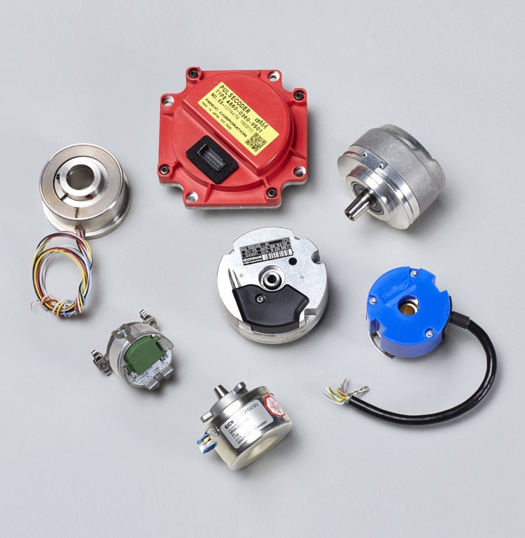
Encoders are sensors that generate digital signals in response to movement.
They are available in two types:
- one that responds to rotation,
- the other to linear movement.
When used in conjunction with mechanical devices such as gears, gauge wheels, or motor shafts, they can be used to measure linear motion, speed, and position.
Encoders are available with different types of outputs:
- Incremental encoders, which generate pulses while moving, are used to measure velocity or position trajectory.
Absolute encoders that generate digital multi-bits, which directly indicate its current position.
Encoders can be used in a wide variety of applications. They act as feedback transducers for speed control in motors, as sensors for measurement, shear and position. Also as input for speed and range controls.
Encoder Examples
Let’s look at some examples:
- Door control device
- Robotics
- Demolition lens machines
- Plotter
- Testing machines
- Ultrasonic welding
- Converting machinery
- Assembly machines
- Labeling machines
- X / y indication
- Analysis Devices
- Drilling machines
- Mixing machines
- Medical equipment

Types of encoders: incremental and absolute
A- Incremental encoder (incremental encoding)
Incremental encoders provide a specific number of pulses equally spaced per revolution (PPR) or per inch or millimeter of linear motion.
- A single output channel is used for applications where the direction of movement is not important (unidirectional).
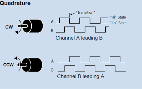
- Where the sense of direction is required, the quadrature (bidirectional) output is used, with two 90-degree electrical channels out of phase; the circuit determines the direction of movement based on the phase of relationship between them. This is useful for processes that can be reversed, or to maintain the net position when it is stationary or mechanically oscillating. For example, machine vibration while it is stopped could cause a unidirectional encoder to produce a pulse current that would be wrongly counted as movement. The controller would not be tricked when using the quadrature count.
Quadrature signals are decoded by specialized circuits that determine the direction of movement based on the phase relationship of channel A to channel B. Quadrature output allows monitoring of processes that can reverse direction, or that must maintain the net position when stopped or mechanically oscillating. Bidirectional quadrature is recommended for most positioning applications, speed and length.

In addition to encoding the output, there are options as to the type of output circuit used for signal transmission. “Current sinking”, “current sourcing” or “push-pull” circuits are used when the signal does not have to travel a long distance and the environment is free from sources of electrical interference. It is important to know the type of circuit to which the encoder can be connected in order to select the appropriate output.
For long distance transmission, and/or when high levels of electrical interference are present, a differential output circuit in the driver is often the best option. This type of interface provides signals A and B plus two additional signals that are its inverse complements (180 degrees electrically displaced). It is capable of driving long transmission lines and by comparing each other’s channel and its complement, common mode interference can be canceled.


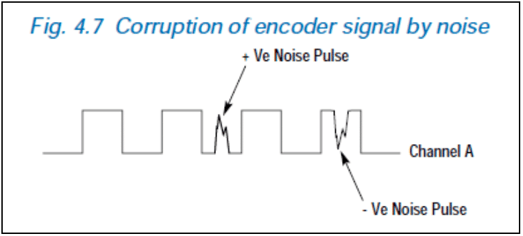
Figure 4.7 shows how the introduction of two noise pulses has converted a four-pulse train into one of six pulses.
Some of the advantages of using incremental encoders are the following:
➜ They are inherently digital and therefore can be easily interconnected with modern devices
➜ They are inexpensive and easy to use
➜ They give you a good resolution in relation to cost
➜ Its differential digital output makes it more immune to noise compared to other feedback devices that provide analog signals
Some of the disadvantages of using incremental encoders are the following:
➜ The incremental quadrature encoder (without switching signals) provides speed and position feedback, but does not provide the switching signal. Therefore the absolute position is unknown. If unit power is lost then position is lost
➜ When compared to a resolution, the operating temperature range is smaller because the electronics are integrated in the encoder return. Encoders continue to operate at temperatures up to 120 °C (100 °C maximum to maintain full performance)
B- Absolute encoder (absolute encoding)
An absolute encoder generates digital messages which represent the current encoder position as well as its speed and direction of movement. If the power is lost, its output will be corrected each time the power is restored. It is not necessary to go to a reference position as with incremental encoders. Electrical transistors can produce only transient data errors, usually too short to affect the dynamics of a system control.
The resolution of an absolute encoder is defined as the number of bits per output message. This output can be directly in binary or Gray code, which produces a single bit change at each step to reduce errors.
The “absolute” type produces a unique digital code for each different angle of the axis.

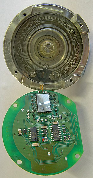
Absolute Gray code encoder with 13 tracks. At the top you can see the receptacle, the switch disc and the light source. At the bottom you can see the detection element and support components.
The resolution of a SinCos encoder is dependent on the frequency of the sine wave signal and the peak-to-peak differential voltage of the encoder.
As with conventional SinCos rotary encoders, a SinCos linear encoder is also available. The linear scale is attached to the frame of the magnetic support plate and the sensor head is mounted on the coil unit. This type of detection head is generally the cheapest form available in optical linear encoders.
Some advantages of SinCos encoders are as follows:
➜ high resolution can be achieved with interpolation within the unit
➜ they are used with Comms encoders to provide incremental signals
Some disadvantages of SinCos encoders are the following:
➜ absolute position is unknown; SinCos encoders are only used for speed increments and feedback position
➜ sensitive to noise due to the analog nature of the feedback signal


